The other day, my household came into the possession of a car boot sale 'bargain' for £3 of a 37-key Casio SA-65 electronic keyboard.
It suffered from a badly corroded battery compartment (actually, the compartment lid is missing and tape was used to hold the 5 x AA for 7.5V supply). The accompanying AC/DC UK wall wart power adapter was a generic Goodman 12V 1.5A device, not exactly a good match.
I re-purposed the AC/DC wall wart for a power supply on my recent Almost All Digital Electronics 10MHz frequency standard (see other posting) and set to work to try and clear the battery compartment of the Casio.
I opened the keyboard up. Here and there was a fishy-smelling brown goop on battery connectors, some through-hole components and casing. Using Naptha as a cleaner, I quickly removed the goop and assessed that the negative battery connector was heavily clogged with a the insides of along-dead AA battery. I desoldered the negative connector and plunged it into a home-made mix of corrosion fighting soups:
- one tablespoon of table salt in a small glass, and diluted with vinegar (I only had sherry vinegar, so my photo is a darker red-brown - that is the vinegar, not any corrosion!)
- a stop-bath of one tablespoon of sodium bicarbonate in water to halt the acid bath
I let the wire steep overnight (6 hours in my house if I am lucky!) in the acid, the plunged it in the base to stop and used a wire brush to remove what remained. The resulting wire is heavily pitted, but conducts well.
With power restored via a bench DC supply, I then discovered the reason that the keyboard was probably left derelict and worthy of a car boot sale: not all keys worked as they should.
Every octave, two adjacent keys are inexplicably tied together: press lower D and you hear D & D#. Press D# and you hear D and D#. Ditto for higher pitch pairs: A# and B, F# and G, then higher still D and D#, A# and B. All other keys are fine.
I was lucky to find the service manual online for the Casio SA-65
here and started my analysis.
The keyboard matrix plan shows that KI5 and KI6 (two of the 8 CPU input pins) connect all the keys above to the 5 CPU output pins (KO0, ..., KO4) that are used to record a musical keystroke (other outputs and input pins record menu select buttons, volume, etc.)
So, why is a note pressed on KO0&KI5 causing the CPU to think KO0&KI6 are connected too (and vice versa, and ditto for KO1, 2, 3 and 4 with these inputs)?
The problem is not in the keyboard nor 'ghosting' that occurs a) when 3 of 4 adjacent keys in the keyboard matrix are pressed, while b) all diodes are 'broken' or not installed (a great explanation is found
over at this site : basically my issue does not fulfill the conditions required for ghosting: all anti-ghosting diodes are in place and working and I am not pressing 3 keys).
Indeed, I desoldered the KI6 cable on the PCB board to establish that the unwanted image of KO0&KI5 that appears on KI6 is NOT coming from the keyboard: with KI6 at the keyboard disconnected from the main PCB, the KI6 was still reaching the CPU. There are no shorts across KI5 and KI6 on the keyboard itself and all diodes are fine. The issue lies on the main PCB somewhere.
Looking at the schematic (see service manual), the only other locations where KI5 and KI6 'get close' is at the CPU. I desoldered the KI6 pin resistor (R127) and still the problem occurs of two notes when KO0&KI5 is closed (lower key D on left side of keyboard).
This places the issue much closer to the CPU itself, or the bypass capacitor that is formed by a 'module capacitor' of 7 0.1nF caps with common ground pin (you can see this from the description as MC101 CNB7x101K = 7 '101' (0.1nF) caps of K tolerance (10%)).
Trial and lots of error
Starting to scratch my head, I am currently exploring two possibilities:
- Ground Bounce
- Bad bypass capacitor
The idea of 2) is based on some uninformed observations (!) by me:
If you ground CPU input KI6, the image note (D#) of KO0&KI5 (D) goes away (yes!), but then no note from KO0&KI6 (D#) occurs since any signal is taken to ground and away from the CPU.
While playing with extra caps in parallel to the on-board caps noted above, I observed that using a KI6 in series with a 10nF cap connected to ground (this cap is then parallel to the on-board 0.1nF cap, and adds capacitance to the bypass circuit) restored the image note (no more DC grounding at pin KI6) but also created a THIRD note (for one keyboard key press) that sounds an octave higher.
Increase that series cap to 100nF and FOUR notes are heard.... what is going on?
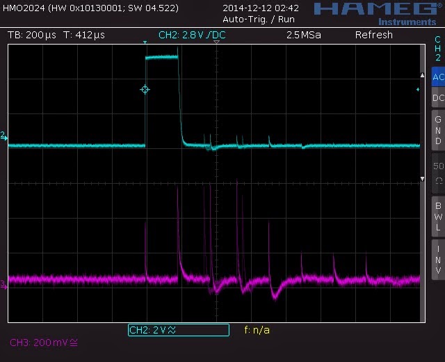
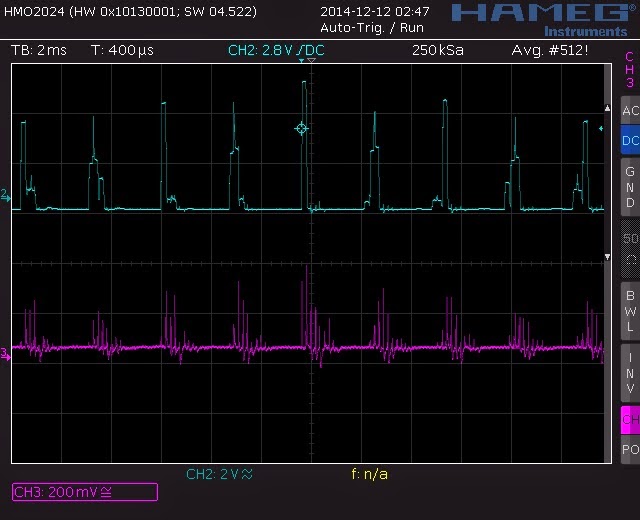
My thinking here has something to do with how the CPU sends out a pulse wave to each output pin. The photo below shows the KO0 pulse output signal from the CPU: 5V pulse, around 350Hz. However, this pulse is not steady and has some jitter, if I judge by the flickering screen on my 'scope.
This jitter means that within each second, there will be pulses a but later (or earlier) that the rising edge of a true steady square wave. The CPU however differentiates an output pin by the relative timing of the pulses, as summarised in the service manual diagram here:
This means the 'key scan signal' on KO0 can be misinterpreted as another output pulse if the square wave is seen at a different time: it might look like a KO1 pin pulse for example (see above image).
This would mean that a KO0&KI5 key press (D) creates a circuit that contains a false KO1 signal, which - according to the keyboard matrix table - is is KO1&KI5 key press = A# (8 notes higher). Presumably, KO2, KO3 and other false pulses will be sent to the CPU on the KI5 input pin, so why are these not heard?
The answer seems to be the amount of capacitance at the bypass to ground. As noted, adding 10nF bypass cap 'reveals' a third note, and making that a 100nF cap reveals a FOURTH note even higher up (which supports the idea of lots of false signals at KI5).
I have not tested all output pins for jitter (I might as well have a look). Perhaps it is not there, hence the reason why the other keys work well.....
The larger bypass capacitance may be explained by its smoothing effect: think of the input pin receiving several square wave pulses out of sync, faking the multiple key presses, which is smoothed to ground. Square waves convert to a sort of triangle/ramp waves when run though bypass caps (
Wiki link for this diagram:
The larger the cap the more spread out the original pulse width becomes since the small caps discharge quicker (so the curved shoulder and toe in the blue line is steeper in transition and appears closer to a square wave). This capacitor spreading affect and the closely spaced/adjacent pulses from output jitter would mean the CPU 'see' significant voltages across the timing of rising edges, which it interprets as many keys pressed, so makes those notes at the speaker.
All that aside, this does not help to understand the reason for a KI6 signal on a KI5 input to the CPU.
The on-board capacitor may be faulty and I am will try to measure it for behaviour
Lastly, the other way to possibly create an issue is Ground Bounce.
This is described
here in a downloaded ppt. The summary seems to be this:
The 'device ground' of a quiescent pin on an IC can be different to the 'electrical ground' of the circuit. Ideally, when a pin is low, it should be 0V in line with the electrical ground. But it seems there are instances where transitions of low/high or high/low voltages , which create current changes (di/dt) can combine, with inherent circuit inductance, induced voltages that move relative voltage levels. In some sense, 0V in an IC can detach from 0V at the power supply. This can pre-load a pin voltage at an IC to be higher or closer to a TTL logic threshold and create phantom signals.
I need to measure a quiet input and output pin on the CPU compared to a high/low or low/high input to see if there is a ripple or bounce in 'device ground'.
There is a broken diode on the PCB board, D104, that shows only a 0.1V forward voltage (not the expected 0.61V for this type of diode) and 0.1V in reverse voltage - this is a significant failing of a diode. This diode exists in the power supply circuit and allows a circuit to exist between analogue ground (AGND) and digital voltage (VDD). Perhaps this allows a ground bounce effect to affect digital signal levels? The analogue ground is related to a transistor pre-amplifier that smooths the CPU waveform into an analogue sine wave, passing it to a 1W power amplifier chip.
Also, looking at the schematic, there bad diode D104 could affect the CPU oscillator (21.725MHz) which might explain the jitter on CPU output timing mentioned above.
I will replace the diode and observe the results.
This is a work in progress, so watch out for a new posting about the next steps.
Thanks for reading.


