Following yesterday's post on the observed issues with a Casio SA-65 electronic keyboard, and my attempts to resolve them, I'm able to make a short post to follow-up on two topic mentioned there: Jitter and Ground Bounce.
I remarked that the CPU has output pins that send a square wave pulse out towards the keyboard - the key scan signal. The keyboard switching arrangement is a matrix, and the CPU listens on input pins for a received signal from a closed circuit, i.e. a piano key being depressed.
 The CPU decides what note to play based upon a) what input pin has a non-zero signal (since all the input pins are quiescent in the absence of a signal) and b) WHEN that square wave pulse is, relative to the CPU's string of pulses sent from each output pin in turn. Imagine your rolling or wrapping your fingers on a table top as you wait impatiently for waiter service to ask for the cheque. Your fingers sequentially tap the table, say little finger first, then ring finger, then middle finger, fore finger and lastly thumb, then back to the pinky finger again....This is the CPU firing pulses at the outputs and where a pulse is, relative to some internal counting or reference pulse, is information used to define the output pin used (see the last post for a picture from the service manual on this point).
I had commented that the KO0 output was jittery,
and last night was able to take a look at that jitter. The screenshot below is a trace of KO0 from my Casio SA-65 CPU. The trace as a static picture is misleading as it suggests uniform periodicity.
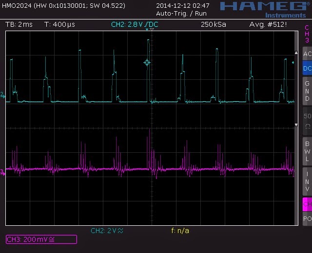
An alternative view of the same event, this time averaged over 512 samples. Since the CPU output pulses for each pin are around 350Hz, this sample of 512 gives an idea of the typical 1.5 seconds of output pin behaviour. We can see dramatically that instead of regimented square wave pulses, the KO0 trace looks like the Manhattan skyline, while the ground bounce is very messy at each square wave event.
CPU output pin jitter
 The CPU decides what note to play based upon a) what input pin has a non-zero signal (since all the input pins are quiescent in the absence of a signal) and b) WHEN that square wave pulse is, relative to the CPU's string of pulses sent from each output pin in turn. Imagine your rolling or wrapping your fingers on a table top as you wait impatiently for waiter service to ask for the cheque. Your fingers sequentially tap the table, say little finger first, then ring finger, then middle finger, fore finger and lastly thumb, then back to the pinky finger again....This is the CPU firing pulses at the outputs and where a pulse is, relative to some internal counting or reference pulse, is information used to define the output pin used (see the last post for a picture from the service manual on this point).
I had commented that the KO0 output was jittery,
and last night was able to take a look at that jitter. The screenshot below is a trace of KO0 from my Casio SA-65 CPU. The trace as a static picture is misleading as it suggests uniform periodicity.
In actual fact, the pulses are a bit all over the place. Below is a screenshot showing the blue KO0 pulses, but as an envelope trace: rather than a single sweep and trace as above, we see multiple sweep traces laid on top of each other - in an analogue oscilloscope, you would get the same effect my increasing the phosphorous persistence rate and let all earlier traces linger on the screen for longer:
Clearly, the KO0 pulses are actually mis-spaced to the extent that the CPU listening to this signal would easily create false key notes by thinking that outputs other than KO0 were connected via piano key pressing.
This jitter supports the analysis made in my last post to explain the many octave notes that lurk in the speaker output, but which are not sent to the CPU pin because of the bypass capacitors connected to ground at the input pins. Increasing the capacitor size, smooths these mixed pulses across wider 'pulse time slots' and allows the CPU to 'see them', and musical notes result.
Ground Bounce
The jitter resolved above is a digression, since it does not answer the reason why the jitter exists in the first place. One idea was the existing bad diode in the power supply circuit, D104.
This bad diode would possibly create problems with CPU oscillations and result in the jitter confirmed above, and also might have a role to play in any ground bounce.
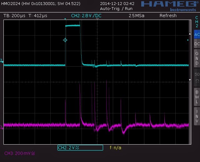
With limited time last night, I was able to look for ground bounce on quiet pins of the CPU. I started by looking at KO0 output pulses (blue) and a KI5 input pin (yellow), which are linked in a closed circuit when depressing the lower D piano key. We see the expected KO0 signal appearing as a copy at KI5 (see below screenshot). However, I monitored an unused input pin, KI0 (purple):
Expectation would suggest the quiet input pin is near 0V, but we see a distinct pulse in sync with the pressed key (KO0&KI5). This is a phantom signal. Indeed, if the peak voltage were higher (it is just over 2V in the trace, compared to 5V for the real signal), we might hear the phantom note at the speaker.
Clearly, the device ground of quiet pins is not so quiet.
Zooming in on the same quiescent input pin, KI0, where there is no piano key depressed, we see that each output pin pulse (using our KO0 in blue trace), we see there are indeed ripples and bouncing when there is a high/low or low/high event. In the shot below, KO0 (blue) fires a 5V square wave pulse. At the same moment, KI0 (purple) feels spikes and ripples in what is technically the CPU ground state:
 |
| KO0 (blue) 2V per division. KI0 (purple) 200mV per division |
An alternative view of the same event, this time averaged over 512 samples. Since the CPU output pulses for each pin are around 350Hz, this sample of 512 gives an idea of the typical 1.5 seconds of output pin behaviour. We can see dramatically that instead of regimented square wave pulses, the KO0 trace looks like the Manhattan skyline, while the ground bounce is very messy at each square wave event.
In summary, the noisy 'device ground' and output pulse jitter suggest strongly a problem of timing in the CPU and clean ground bias. As was seen in earlier in this blog, even unrelated input pins like KI0 can appear to have significant square wave signals that might be interpreted as key strokes on the piano. [Note: KI0 is physically furthest from the KI5 pin I have studied, yet still carries a 2V peak pulse. KI6, which does yield audible note production (it has nearly 5v peak signals (see last post picture) is next to KI5. Perhaps physical proximity of pins on the CPU is the reason why KI6 is heard with KI5, given some initial biasing that the other pins do not have.... KI5 and KI6 are furthest from the CPU ground pin, for example....].
That bad diode D104 is the next task to try to repair this electronic keyboard.


No comments:
Post a Comment